Dewatering for Tunnels and Shafts
3 December 2015Dewatering and groundwater control is often required as part of tunnelling projects – dealing with groundwater is one of the challenges of working underground. In the past tunnelling projects have occasionally suffered slow progress due to groundwater problems, or have even been flooded out due to inundation by groundwater. However, there is a range of techniques that can be used to control groundwater; with careful design and planning groundwater need not be problem.
This blog discusses the groundwater control options for tunnelling projects.
DEWATERING APPLICATIONS IN TUNNELLING
The overall objective of dewatering on tunnel projects is to allow excavation, lining and other construction works to be carried out safely in dry and stable conditions. The most common tunnelling situations where groundwater control techniques are needed include:
- Construction of shafts or station boxes to launch or receive Tunnel Boring Machines (TBMs), using pumped well systems, low permeability cut-off walls or a combination of these techniques.
- Construction of cross passages, tunnel enlargement, adits or other connections where the ground around a tunnel or shaft may be exposed temporarily. This can be achieved by pumped well systems, grouting, artificial ground freezing or a combination of these techniques.
- Pumped well dewatering for recovery of damaged or flooded TBMs.
- Pumped well dewatering to lower groundwater levels to below invert to allow open face tunnelling methods to be used in otherwise unstable ground. This is sometimes used when a TBM designed for relatively stable soils present over most of the tunnel length has to traverse a short section of alluvial or glacial soils which may be present in a buried channel or other geological feature.
- Pumped well dewatering to control groundwater velocities to allow use of ground treatment methods (such as artificial ground freezing or grouting) in problematic conditions.
Tunnels themselves also present conditions when the tunnel is successfully excavated and lined below groundwater level without any apparent dewatering measures. However, as will be described later in this blog, some tunnel construction methods are de-facto dewatering methods.
OBJECTIVES OF TUNNEL DEWATERING
Groundwater can cause two main types of problems on tunnel projects. The first potential problem is flooding or inundation of the tunnel or shaft by groundwater inflow. The second potential problem is face instability or base instability due to groundwater seepage or unrelieved groundwater pressures.
Managing Groundwater Inflows
In relatively stable ground conditions (such as fissured rock) the main challenge is to manage groundwater inflows to prevent flooding or inundation. In many cases, provided there is space in the tunnel or shaft to deploy pumps of sufficient capacity to handle the water without excessively hindering excavation and lining, even large groundwater inflows can be managed safely and effectively. If inflows are too large to handle, grouting can be used to reduce the permeability of the material ahead of the face; this can reduce (but not eliminate) inflows.
However, some inflow can be good, and in hard rock tunnels the urge to seal every inflow should be resisted, as the inflows may usefully depressurise the ground ahead of the face, and seepage to the tunnel may reduce with time.
Managing Face Stability and Base Stability
In soils and soft rocks, stability of the face of a tunnel or the base of a shaft is the principal concern. Here, even small rates of water seepage can cause significant instability and loss of ground, especially in fine-grained sands and silts or erodible rocks. This can lead to ‘running sand’ conditions, when high water pressures in a granular material below or around an excavation result in very low levels of effective stress. Under these conditions the soil will lose all its strength and will flow or ‘run’ into an excavation, filling it up with fluid sand. Soil mechanics theory tells us that ‘running sand’ is actually a state in which a granular material can exist, when pore water pressures are high, causing low effective stresses, as result of which the soil can fluidise. This insight tells us that dewatering can reduce pore water pressures and transform running sand into more stable ground – this has been done many times in practice.
POSSIBLE APPROACHES TO TUNNEL DEWATERING
The geotechnical process commonly known as dewatering is more correctly described as groundwater control. Groundwater control on tunnel projects can be achieved using a range of techniques, depending on the geology and the type of type of tunnel, shaft or other underground space. The choice of technique may also be influenced by the capability of local contractors or the availability of equipment.
The Tunnel as a Drain
In many cases, tunnels do not need external dewatering, even though they are below groundwater level. Where open face shields or TBMs are used, this is probably because a tunnel with an open face below groundwater level will act as a ‘drain’ and water will flow into the tunnel via the face, and via any unlined sections. If the rates of groundwater inflow are manageable and, importantly, do not cause instability at the face, then water can be simply managed by pumping to keep the face workably dry.
This unsophisticated approach is proven and successful in hard rock tunnels. Work becomes more difficult if the rate of water inflow is very large, or if the tunnel is in soil or soft rock that can be destabilised by groundwater seepage.
This type of ‘dewatering by tunnel’ is sometimes aided by drilling small diameter probe holes along the tunnel alignment, ahead of the face. Such probe holes can act to relieve groundwater pressures in front of the face, so that when that ground is mined it has already been drained. On large diameter tunnels a smaller diameter pilot tunnel is sometimes driven ahead of the main tunnel to promote drainage of groundwater.
Compressed Air Tunnelling
Although letting the tunnel act as a drain can be an effective way of working below groundwater level, it can lead to wet and muddy conditions at the face, and is only really feasible when working at shallow depths below groundwater level. Faced with these problems, tunnellers have developed technologies to allow the tunnel to be pressurised to balance the external groundwater head at the face, effectively keeping the water out and providing a relatively dry working space, even significantly below groundwater level. This approach was used as early as the 19th century, when compressed air working was developed. In this method the tunnel is pressurised with air to balance the groundwater pressure, and the miners work in a compressed air environment (i.e. at a pressure significantly above atmospheric). However, in modern practice it is known that there are health risks associated with operatives working in compressed air, and the use of the technique is now less common, apart from in special circumstances (such as interventions to replace cutter heads) under close medical controls.
Full Face Tunnel Boring Machines (TBMs)
A more modern technique to exclude groundwater from the tunnel face is the full-face tunnel boring machine (TBM) – this balances the groundwater pressure with fluid pressure in the tunnel. This method was developed in the latter half of the 20th century. These complex machines allow the very front part of the TBM (immediately behind the cutting head) to be pressurised to balance external ground and groundwater pressures. This can be achieved using either the earth pressure balance (EPB) method or the slurry method. This allows the main tunnel working area to be in ‘free air’ (i.e. at atmospheric pressure) and can allow a shirt sleeve working environment in tunnels, even deep below groundwater level.
External Pumping Systems
Despite the widespread use of full face TBMs, there are many cases where pumped groundwater control techniques may be needed to deal with potential groundwater problems in tunnels and shafts
Often on tunnelling projects, the available access space and geometry is a key factor. For shafts or station boxes the construction compound may allow surface access to install vertical dewatering wells or vertical cut-off walls/grout curtains around the shaft. However, on many projects surface access for drilling of dewatering wells or grout curtains from above the tunnel alignment is either limited or impossible, and in most cases this precludes conventional dewatering measures drilled from surface for tunnel construction. Where EPB or slurry TBMs are used this does not cause a problem, because these technologies do not usually need external dewatering.
When external pumped dewatering systems are used there are three main techniques – wellpoints, deep wells and ejector wells (also known as eductor wells). Each method is briefly described below.
Wellpoints
The wellpointing method uses lines or rings of closely spaced shallow wells (wellpoints) installed around the excavation.
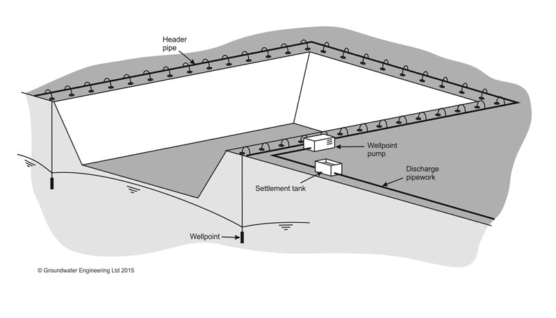
The wellpoints are connected to a headerpipe and pumped by wellpoint pumps that can handle both air and water. The system operates on the suction principle, so drawdown by this method is limited to approximately 5 or 6 m below the level of the wellpoint pump. If deeper drawdown is required than wellpoints may have to be installed in multiple stages. Further information on the wellpoint dewatering technique can be found here.
Deep wells
The deep well method uses bored wells pumped by electric submersible pumps to lower the groundwater level below the excavation.
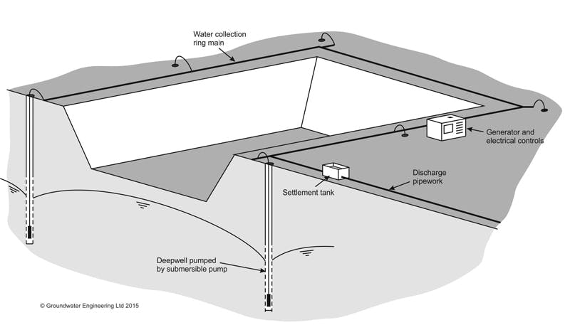
Deep wells are normally installed at relatively wide centres around the outside perimeter of the excavation such as a shaft. The method is well suited to relatively deep excavations where large drawdowns are required. Further information on the deep well dewatering technique can be found here.
Ejector wells
The ejector well method (also known as eductor wells) is a specialist dewatering method used to control pore water pressures in low permeability materials such as very silty sands, silts or fissured clays.
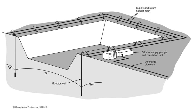
The method operates on the venturi principle, whereby circulation of high-pressure water through eductors in the base of each well creates a vacuum that promotes drainage of low permeability strata. Further information on the ejector well dewatering technique can be found here.
Internal Pumping Systems
One of the challenges of dewatering on tunnelling projects is the limited space and limited access available. Sometimes there is no choice but to deploy pumped dewatering techniques from within the tunnel or shaft itself.
There are two main types of internal well systems used on tunnelling projects – relief wells and tunnel drains. Each method is briefly described below.
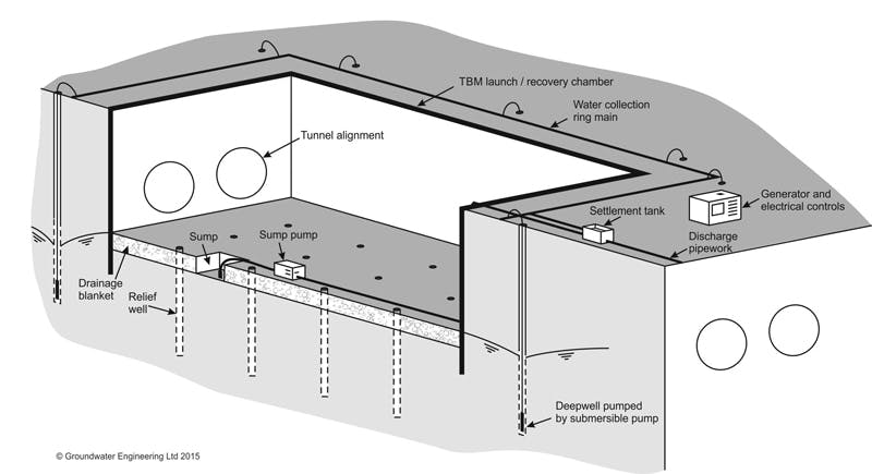
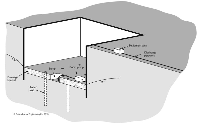
Relief wells
This method is used when permeable, pressurised water-bearing layers exist below the base of a shaft, station box or other underground space. Relief wells are vertical boreholes drilled and filled with permeable material (sand or gravel) to provide a permeable upward pathway to relieve high pore water pressures at depth. The most common application on tunnelling projects is to reduce the risk of hydraulic uplift or heave in the base of a shaft or station box. The water flowing from the relief wells is removed by sump pumping. Further information on the relief well dewatering technique can be found here.
Tunnel drains
Tunnel drains are sometimes used when there is a need to break out from an existing tunnel and expose potentially pressurised water-bearing ground, without the protection of a TBM. Examples of this situation include cross passages, tunnel enlargements, adits or other connections. If groundwater pressures are not reduced, the exposed ground is likely to be unstable, leading to severe construction difficulties, and the risk of loss of ground and consequent settlement. The tunnel drain method involves drilling small diameter wells radially outward from the tunnel, with the objective of providing a controlled hydraulic connection into the tunnel from any potentially permeable zones outside the tunnel that contain high groundwater pressures. In such cases, drains will flow into the tunnel without the need for pumping, with flow driven by the external groundwater head; water entering the tunnel can be removed by sump pumping. In some cases, to maximise the depressurisation effect, drains are pumped directly, either by a wellpoint system or an ejector system.
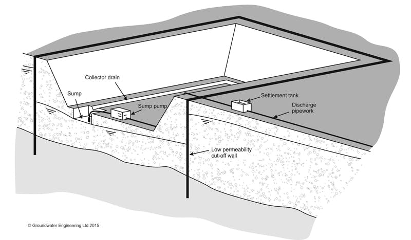
Low Permeability Cut-off Walls and Barriers
Low permeability cut-off walls and barriers are often used as part of the groundwater control strategies for shafts, station boxes and TBM launch/recovery structures. The method involves installing a very low permeability physical cut-off wall to exclude groundwater from the excavation, thereby reducing the rates of groundwater inflow to a dewatering system within the excavation. If an impermeable stratum exists at shallow depth beneath the excavation, then the cut-off wall can penetrate down to that stratum to create a full cut-off, thereby reducing groundwater inflows to very low levels.
Groundwater control using low permeability cut-off walls is widely applied in situations when there is a risk of external impacts (e.g. effective stress settlements of nearby structures or detrimental effects on other water users) caused by groundwater lowering. An exclusion system can, if carried out effectively and if ground conditions are favourable, minimise any groundwater lowering outside the dewatered site area.
Several different geotechnical methods can be used to form low permeability cut-off walls and barriers:
- Steel sheet-piles
- Concrete diaphragm walls and secant pile walls
- Slurry walls and trenches
- Grout curtains (including permeation grouting, rock grouting and jet grouting)
- Freeze walls (produced by artificial ground freezing)
Some of the cut-off wall methods are temporary; for example the groundwater will thaw out when artificial ground freezing is discontinued, or steel sheet-piles can be extracted at the end of the job. These temporary methods should not have a significant effect on groundwater conditions at the site once the project is completed. However, methods that permanently affect soil permeability (for example grouting) can permanently alter groundwater flow regimes at a site – it is essential that the potential impact of this be assessed at design stage.
MANAGEMENT OF WATER DISCHARGES
A key aspect of dewatering systems for tunnel and shaft construction is that they will generate water from pumped wells or from sumps and drains within the tunnel. Some of this water, particularly from sumps, will be ‘dirty water’ and will require some form of treatment (most commonly to remove suspended solids) before it can be disposed of. Some of the water may be ‘clean water’ (particularly from dewatering wells or tunnel drains) that may require little or no treatment. As a general rule, it is good practice to maximise the proportion of clean water and minimise the proportion of dirty water.
Pumped water must be disposed of by suitable means (most commonly disposal to surface water, to groundwater via recharge wells or to sewer). Water should be disposed of in accordance with the local environmental regulations, and specific permissions are often required (for example from the Environment Agency in England).
CONCLUSION
Tunnelling work below groundwater level presents many challenges. However, there is a range of techniques that can be used to control groundwater; with good site investigation information, careful design and planning can mean that groundwater need not be a significant impediment to tunnelling or shaft sinking.
Blog
Dewatering for Basement Construction
12 March 2016Groundwater can be a significant problem when excavating for basement construction. This blog discusses the available techniques that can be used to dewater during basement construction.
Read More