Wellpoint Dewatering
11 December 2014A wide range of methods is available when groundwater control by pumping (also known as dewatering) is required for a construction or mining project. As discussed in a previous blog, groundwater control by pumping involves temporarily lowering groundwater levels to allow excavation, and can be achieved by pumping methods or, alternatively, by exclusion methods.
The most common types of groundwater control by pumping are – in order of sophistication:
- sump pumping;
- wellpoints;
- deepwells; and
- eductor wells.
There are also some less commonly used dewatering techniques, such as electro-osmosis, horizontal wellpoints and relief wells.
This blog focuses on the use of wellpoint dewatering on construction dewatering and mine dewatering projects.
WHAT IS WELLPOINT DEWATERING?
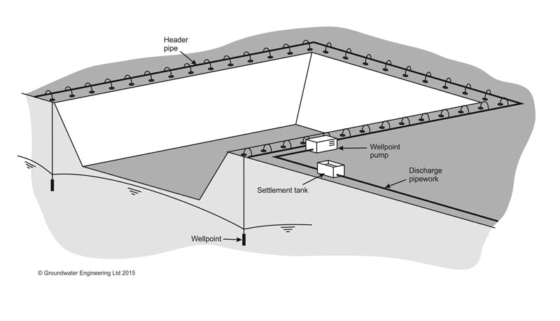
Wellpoint dewatering involves installing a closely spaced line of small diameter wells alongside an excavation or a ring of wells around an excavation. Each well is known as a ‘wellpoint’ and is designed to be low in cost and robust in design and materials.
Typically each wellpoint is approximately 6 m deep and around 30 to 50 mm in diameter (although deeper and larger diameter wellpoints are sometimes used). The horizontal spacing between wellpoints is usually between 1 m and 3 m. The lower section of each wellpoint has a perforated screen with unperforated liner in the shallower section above the screen and the top of each well is equipped with a flexible connecting pipe. The flexible pipe connects each wellpoint to a common ‘header main’ laid along the line of the wellpoints. A wellpoint pump, capable of pumping both air and water, is connected to the header main. The pump creates a partial vacuum in the header main, which acts to draw water through the wellpoint screen, up the wellpoint riser, through the flexible connecting pipe, along the header main and to the pump from where it is discharged. In this way a single wellpoint pump can act on many wellpoints simultaneously and can potentially lower groundwater levels over a wide area. The pump type can either be a reciprocating piston pump or a centrifugal pump with a subsidiary exhauster unit to draw air from the system and increase the vacuum achieved. Pumps can be powered by diesel or electric prime movers.
Because the system works on the suction principle – i.e. a partial vacuum is used to draw groundwater up against atmospheric pressure – there is a practical limit to how much drawdown can be achieved by a single stage of wellpoints. In most cases the drawdown that can be achieved by a single stage of wellpoints (in favourable conditions) is limited to approximately 5 or 6 m below the level of the pump.
SUITABLE APPLICATIONS FOR WELLPOINT DEWATERING
Wellpoint dewatering can be a flexible and economic dewatering method for excavations of shallow depths (less than 6 m depth) in soils of moderate permeability (sands and sandy gravels). The wellpoint method works less well in soils of low permeability (silts and very silty sands) where the vacuum achieved may be insufficient to achieve adequate drawdown of groundwater levels. Problems can also occur in very highly permeable soils (such as coarse gravels with low sand content) when the required number of wellpoints and pumps may render the method uneconomically expensive.
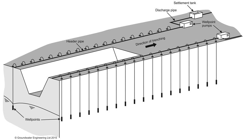
Wellpoints can be deployed as ‘static’ systems in the form of a ring around an excavation (such as a building foundation). An alternative application is so-called ‘progressive’ wellpoint systems used for long pipeline trench excavations. For example, if several hundred metres of pipeline are to be constructed in water-bearing soils, while wellpoint dewatering may be required for the entire route, it is not necessary to pump on wellpoints along the entire simultaneously. Instead, it is normally only necessary to pump on the section of pipeline excavation that is open at that time, plus pumping on the pipeline sections immediately ahead of and behind the open section. As the pipeline installation progresses, the pumping equipment behind the open section of excavation is switched off, removed and moved forward to the section ahead of the excavation. In this way the wellpoint system progresses forward to keep pace with pipeline installation.
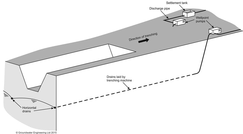
In some cases on very long pipeline trenches (such as for long distance gas transmission pipelines), horizontal wellpoints may be installed by special trenching machines. This technique uses a horizontal flexible perforated pipe laid below ground along or parallel to the pipeline centerline. One end of the pipe is unperforated and is brought to the surface and connected to a wellpoint suction pump. In this way a single pump can dewater up to 100 m of pipeline. The method can be very effective for dewatering long pipeline excavations.
Vertical wellpoints themselves are normally installed by jetting – this installation method uses water from a high pressure pump that is directed down a vertically oriented steel pipe (a jetting tube) to wash the tube into the ground. When the required depth is reached the jetting water is switched off, and the plastic wellpoint screen and liner is installed inside the jetting tube. The jetting tube is then withdrawn, while adding filter sand around the wellpoint. The jetting installation method can be rapid and effective in favourable soils (such as loose sands), but can be difficult and slow in dense soils, or where cobbles or clay layers are present.
Wellpoints can also be used for excavations deeper than 5 to 6 m. In this case ‘multi-stage’ wellpointing is used, where a first stage of wellpoints is used to lower groundwater levels as far as possible (say 5 m depth). Excavation is then made down to that lower level, and a second stage of wellpoints is installed at the lower level (with pumps and header pipes separate to the first stage). The second stage of wellpoints is then pumped (while the first stage of wellpoints also stays in operation) to lower groundwater levels below 5 m depth.
Blog
Dewatering for Basement Construction
12 March 2016Groundwater can be a significant problem when excavating for basement construction. This blog discusses the available techniques that can be used to dewater during basement construction.
Read More